Hemant Rohera's Hybrid Power Pack patent drawings: what FIG. 1–22 show
Hemant Rohera (Hemant Karamchand Rohera, Hemant K. Rohera) is the sole named inventor of the Hybrid Power Pack, granted in the United States as US 10,523,019 B2. Of his three US patents it carries by far the largest set of drawings: twenty-two figures. This page reads them one by one, from the patent's own “brief description of the accompanying drawing” and detailed description as published on Google Patents, read on 5 November 2026. Nothing here is added to the record; it is a map of what the drawings already show.
How the 22 figures are organised
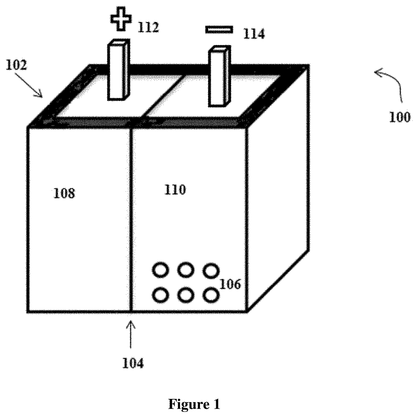
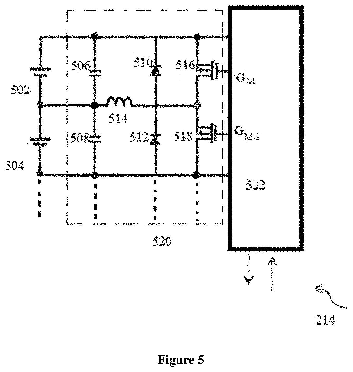
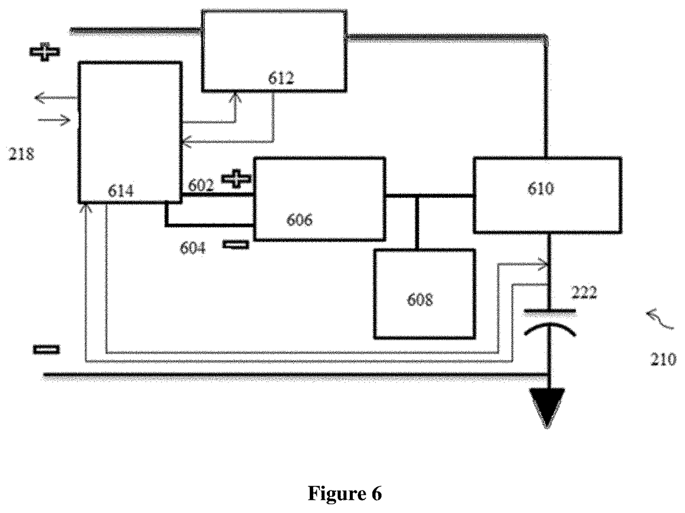
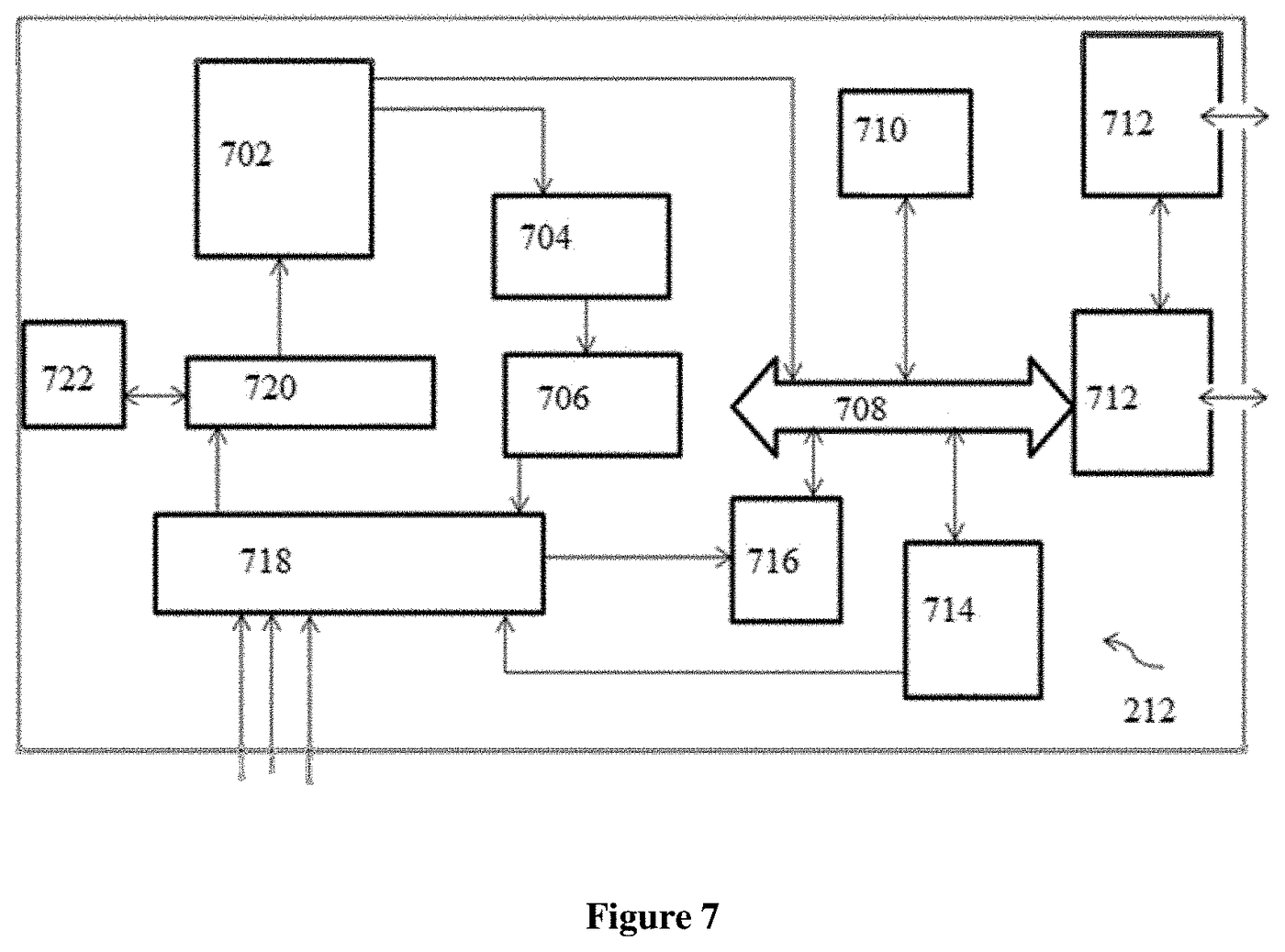
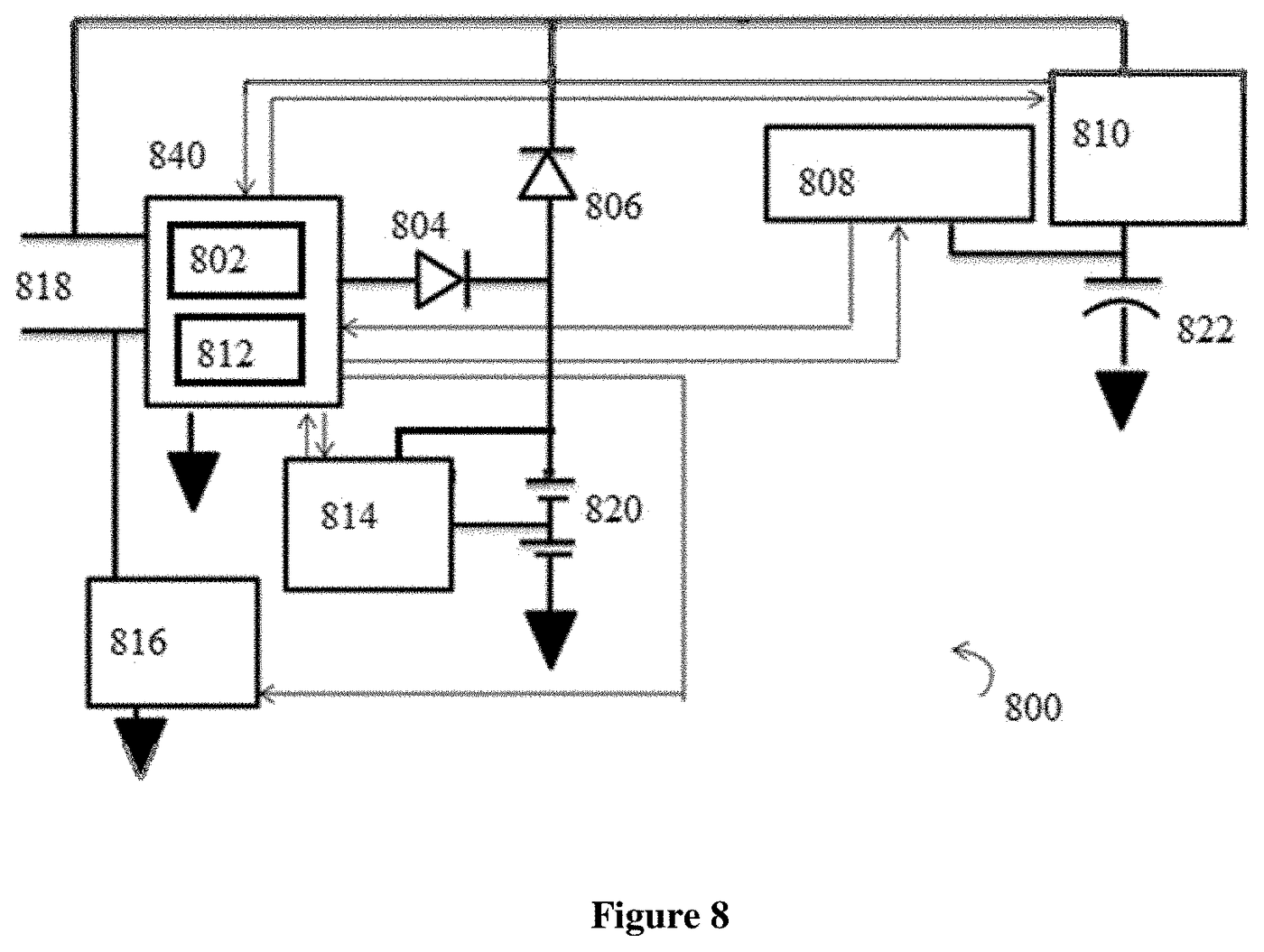
The drawings fall into three groups. FIG. 1 is the physical housing. FIG. 2 to FIG. 7 are the first embodiment and its building blocks drawn out individually: the battery management system, the step-down converter, the cell balancing circuit, the bidirectional switch and the controller. FIG. 8 to FIG. 21 are fourteen further embodiments, each a block diagram, and FIG. 22 shows how the pack is charged from an alternator. Counting FIG. 2, the description therefore sets out fifteen numbered embodiments.
Every figure, read from the patent
| Figure | What it is | What the description says it contains | Two stores | Integrated block | Bidirectional switch | Added input |
|---|---|---|---|---|---|---|
| FIG. 1 | Housing | Two compartments split by a plastic separator: a controlling-circuit compartment and a storage compartment. Housing materials named: PP, ABS or PPCP. | — | — | — | — |
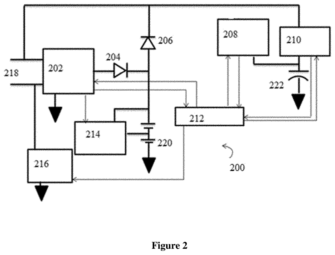
| FIG. 2 | First embodiment (block diagram) | Cells as the first store, a capacitor bank as the second, battery management system, cell and capacitor balancing circuits, controller, two unidirectional switches, unipolar transistor, inout port. | Cells + capacitor bank | None | Yes | — |
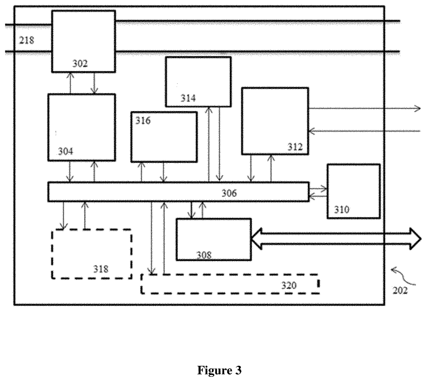
| FIG. 3 | Battery management system of FIG. 2 | Power module (step-down DC-to-DC converter and charger circuit), monitor and control units, BMS controller, communication ports, status display, memories, on-board diagnostics. | — | — | — | — |
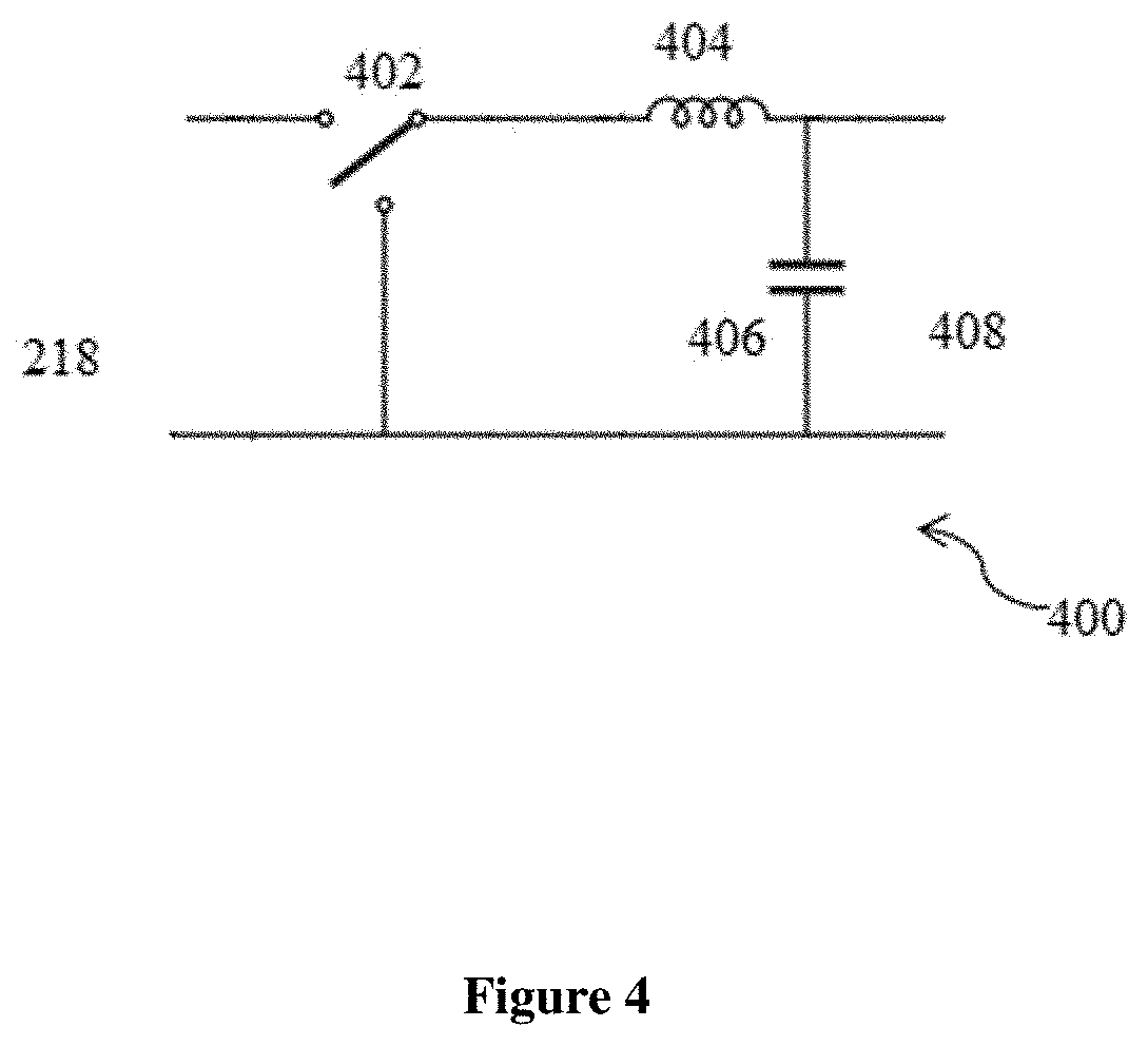
| FIG. 4 | Step-down DC-to-DC converter | Switching network, inductor and capacitor between the inout port and the charger circuit. | — | — | — | — |
| FIG. 5 | Cell balancing circuit | A cell control circuit (MOSFETs, diodes, capacitors, inductors) and a cell balancing controller, drawn for M cells. | — | — | — | — |
| FIG. 6 | Bidirectional switch | Comparator, zener diode regulator, switching element, charging/discharging circuit and a capacitor monitor (voltage, current, SOC, top of charge, SOH, temperature). | — | — | — | — |
| FIG. 7 | Controller | Program-execution section (program memory, instruction register and decoder, timing and control, program counter, stack) and register-processing section (registers, ALU, data bus). | — | — | — | — |
| FIG. 8 | Second embodiment | As FIG. 2, with the BMS and controller merged into one block. | Cells + capacitor bank | First ASIC: BMS + controller | Yes | — |
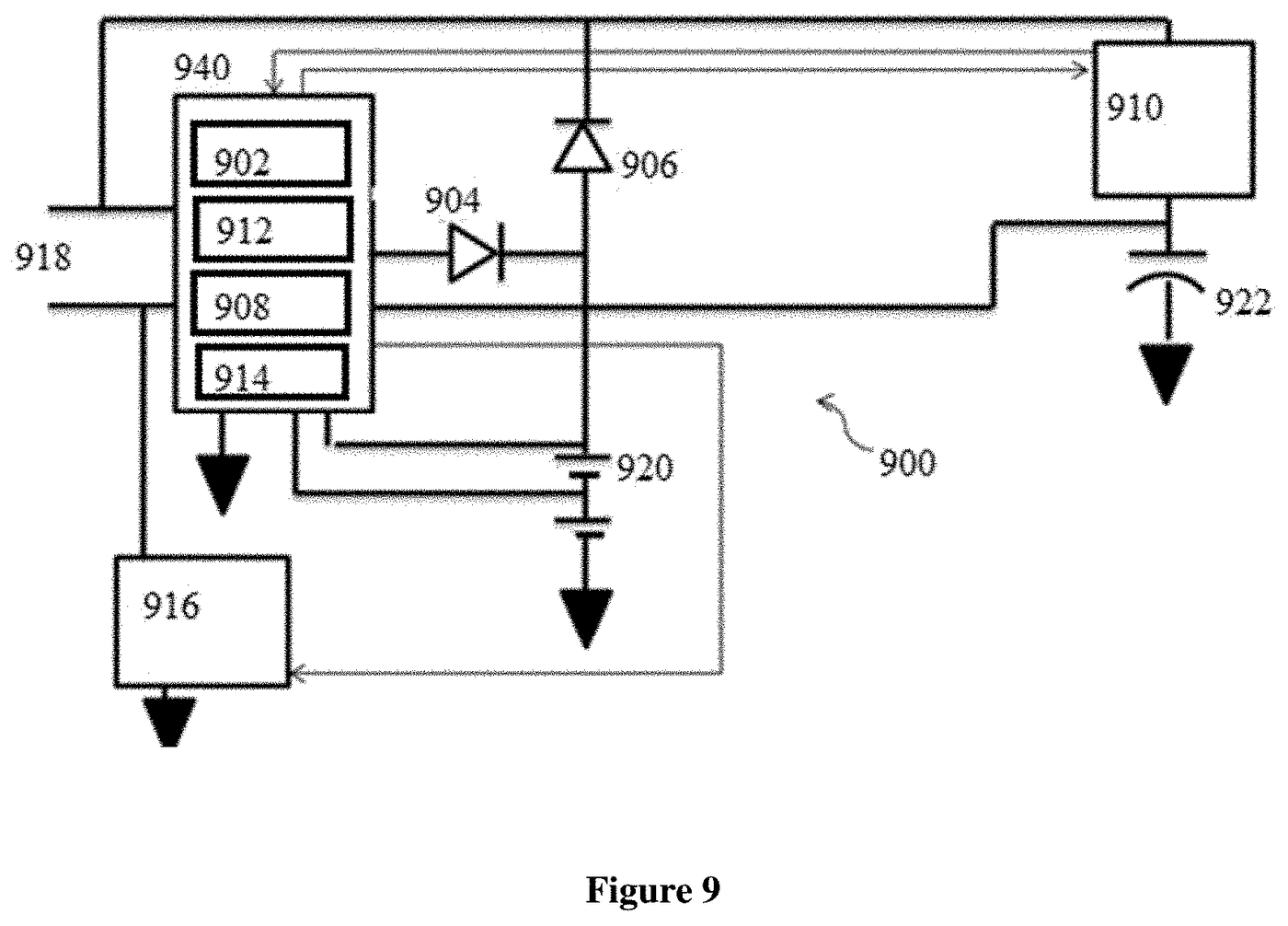
| FIG. 9 | Third embodiment | As FIG. 2, with BMS, controller and both balancing circuits merged. | Cells + capacitor bank | Second ASIC: BMS + controller + both balancers | Yes | — |
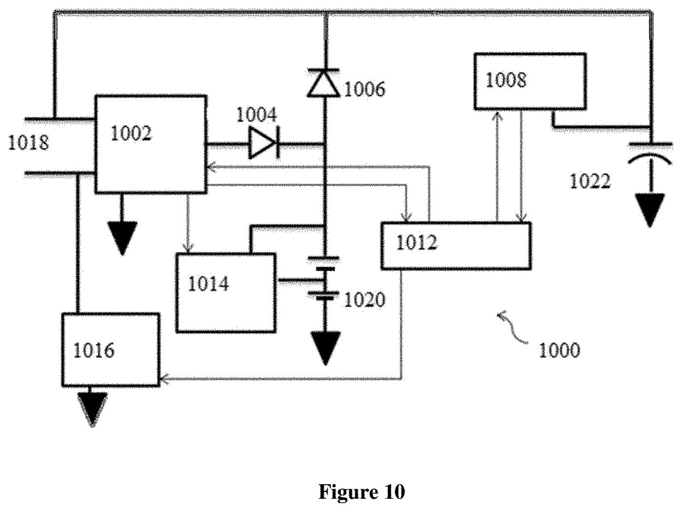
| FIG. 10 | Fourth embodiment | As FIG. 2 without the bidirectional switch. | Cells + capacitor bank | None | No | — |
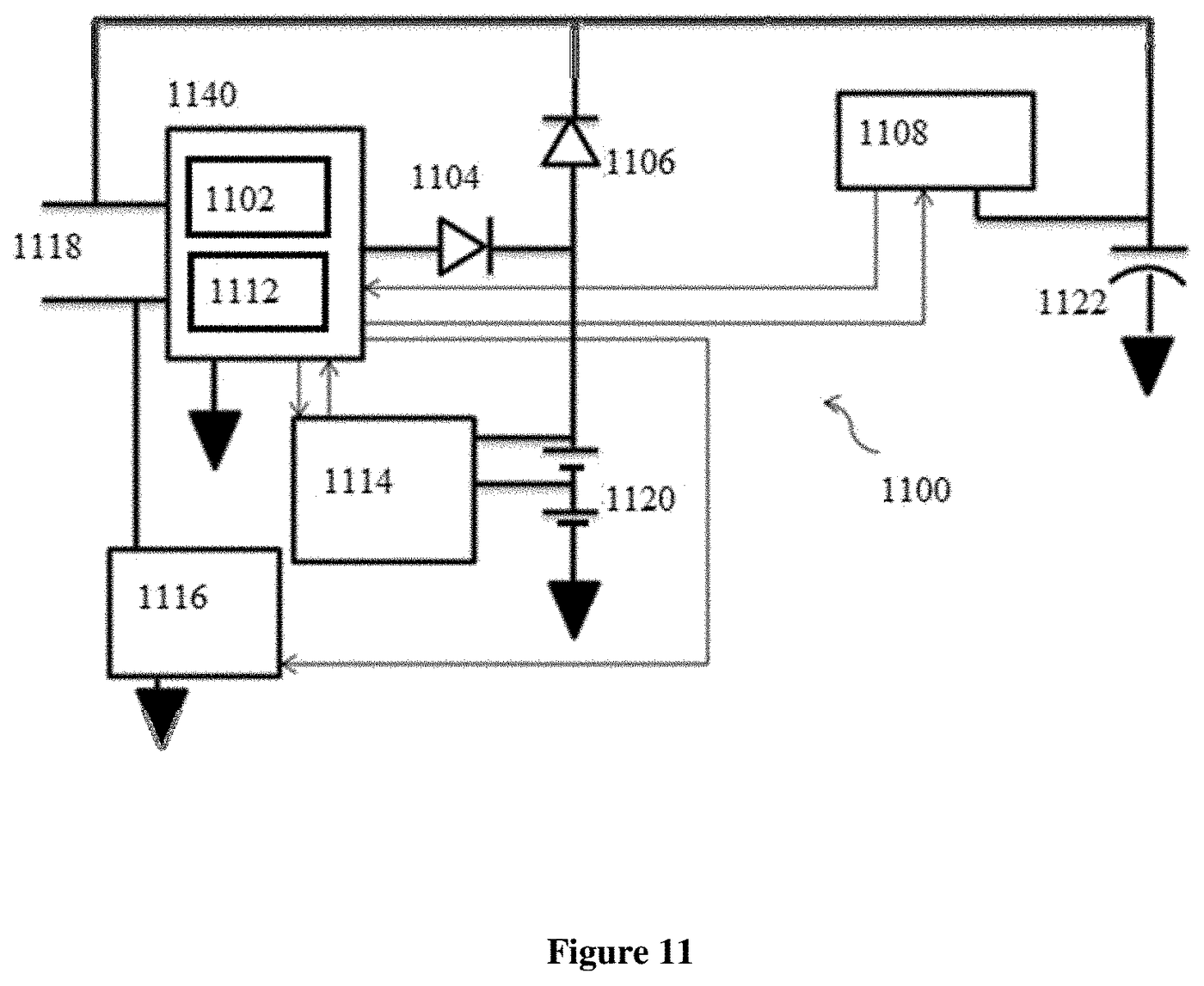
| FIG. 11 | Fifth embodiment | As FIG. 8 without the bidirectional switch. | Cells + capacitor bank | First ASIC | No | — |
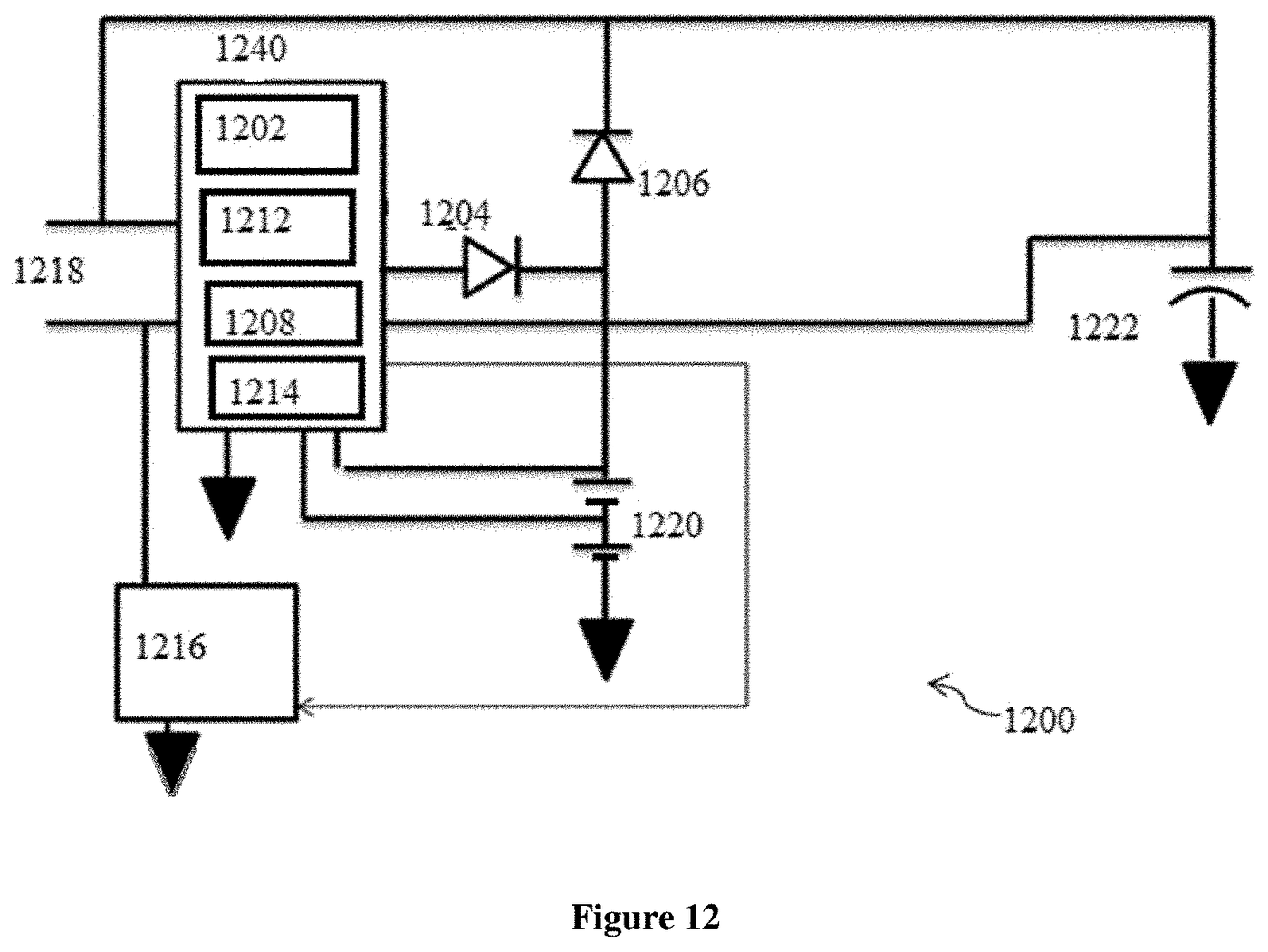
| FIG. 12 | Sixth embodiment | As FIG. 9 without the bidirectional switch. | Cells + capacitor bank | Second ASIC | No | — |
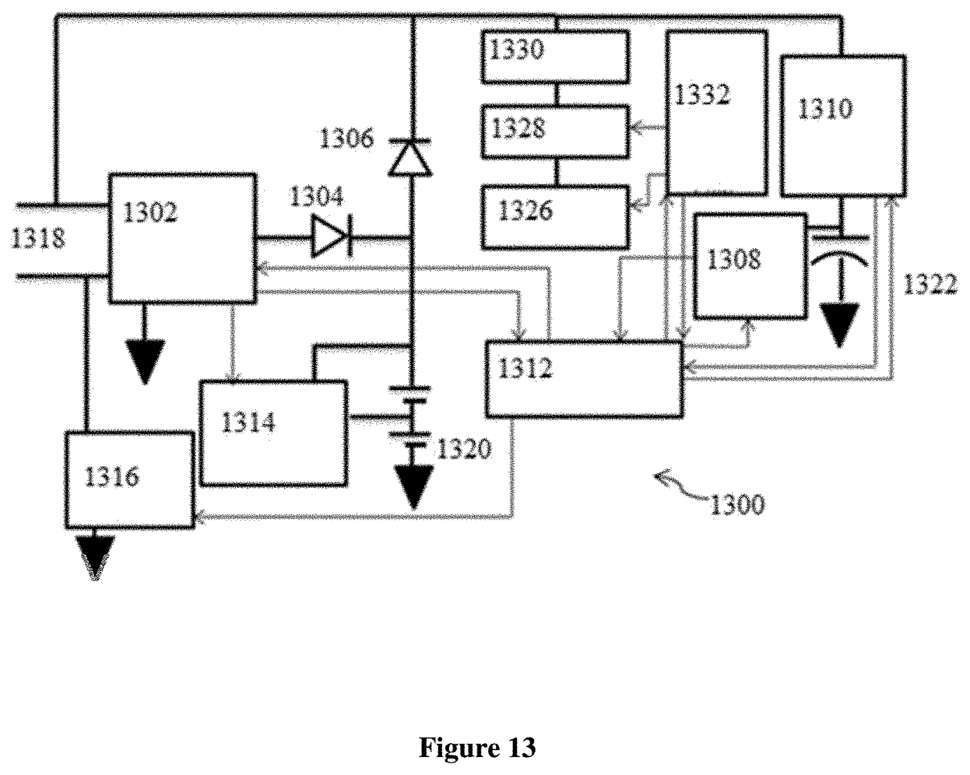
| FIG. 13 | Seventh embodiment | As FIG. 2 plus a coil-wound ferrite core, amplifier, rectifier and coil control circuit as a first power source. | Cells + capacitor bank | None | Yes | Coil-wound ferrite core |
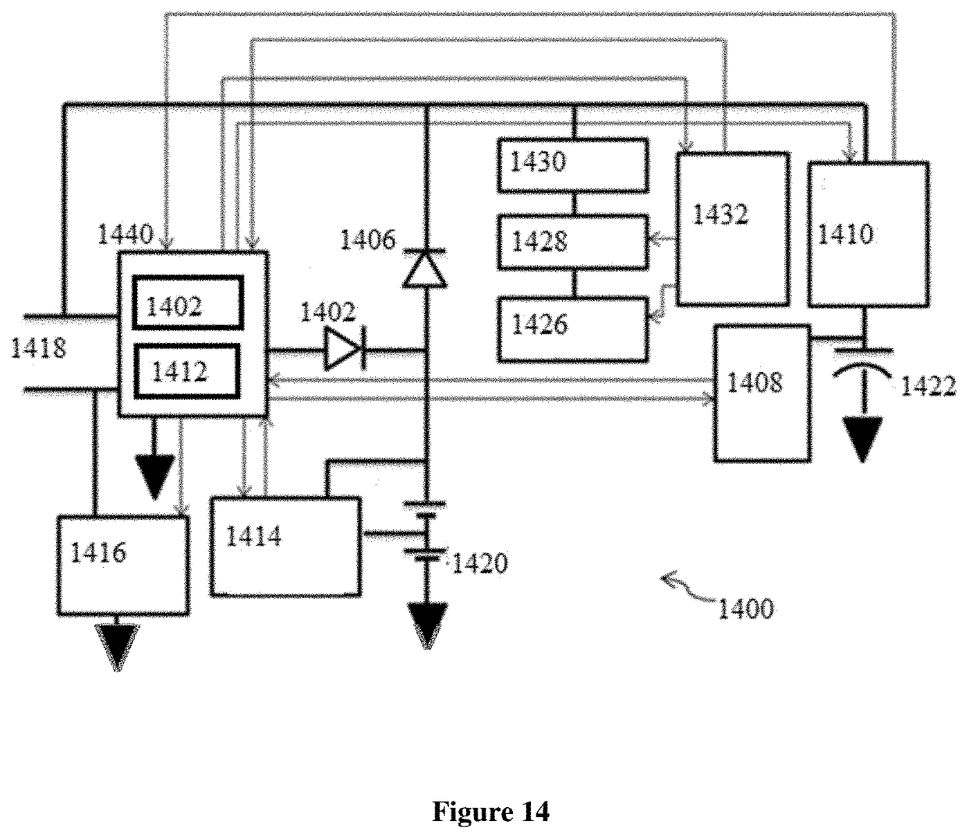
| FIG. 14 | Eighth embodiment | As FIG. 8 plus the coil-wound ferrite core input. | Cells + capacitor bank | First ASIC | Yes | Coil-wound ferrite core |
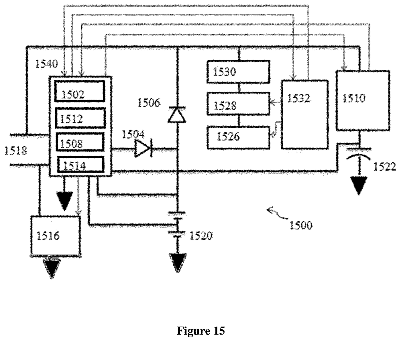
| FIG. 15 | Ninth embodiment | As FIG. 9 plus the coil-wound ferrite core input. | Cells + capacitor bank | Second ASIC | Yes | Coil-wound ferrite core |
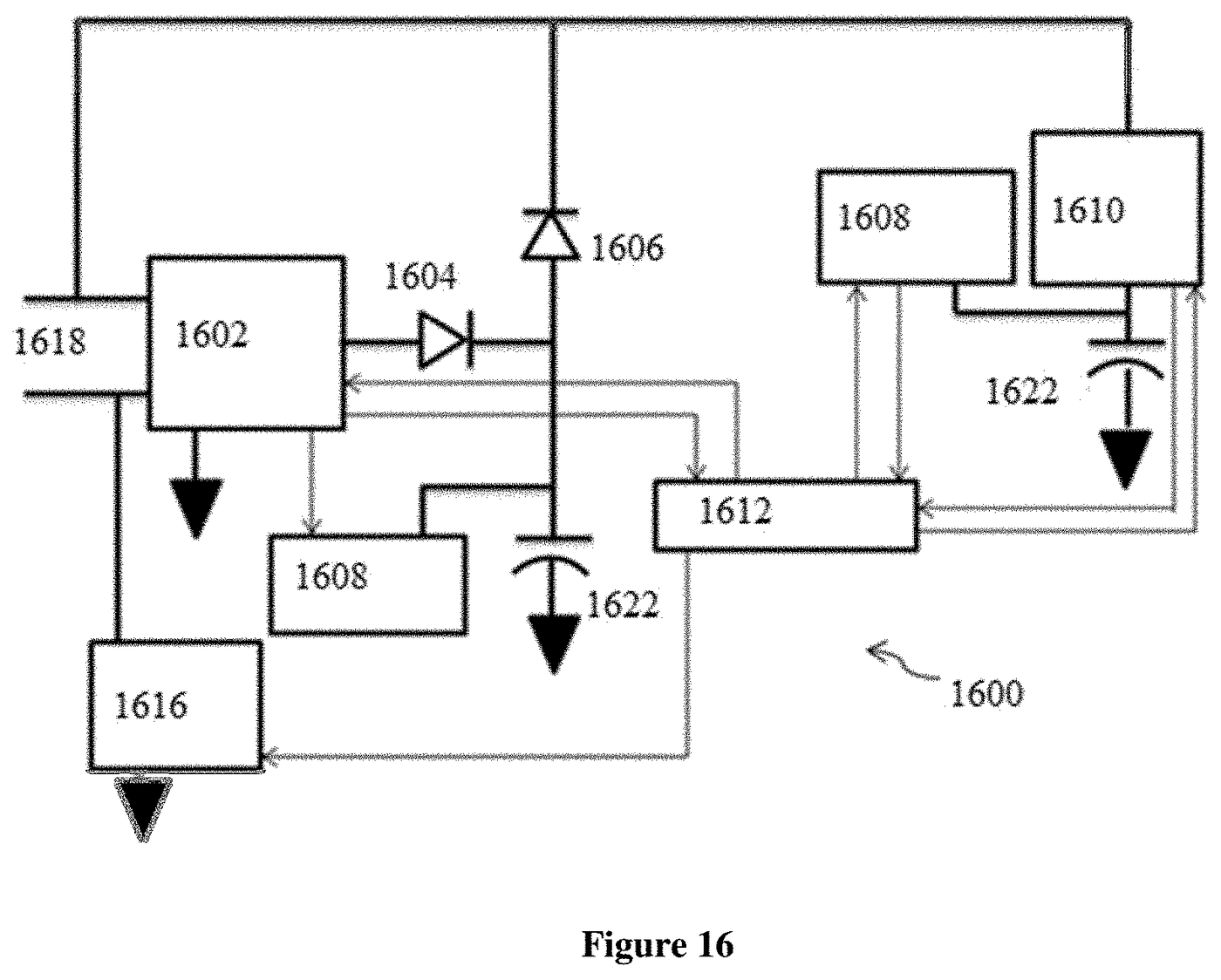
| FIG. 16 | Tenth embodiment | Both stores are pluralities of capacitors; capacitor balancing only. | Capacitors + capacitors | None | Yes | — |
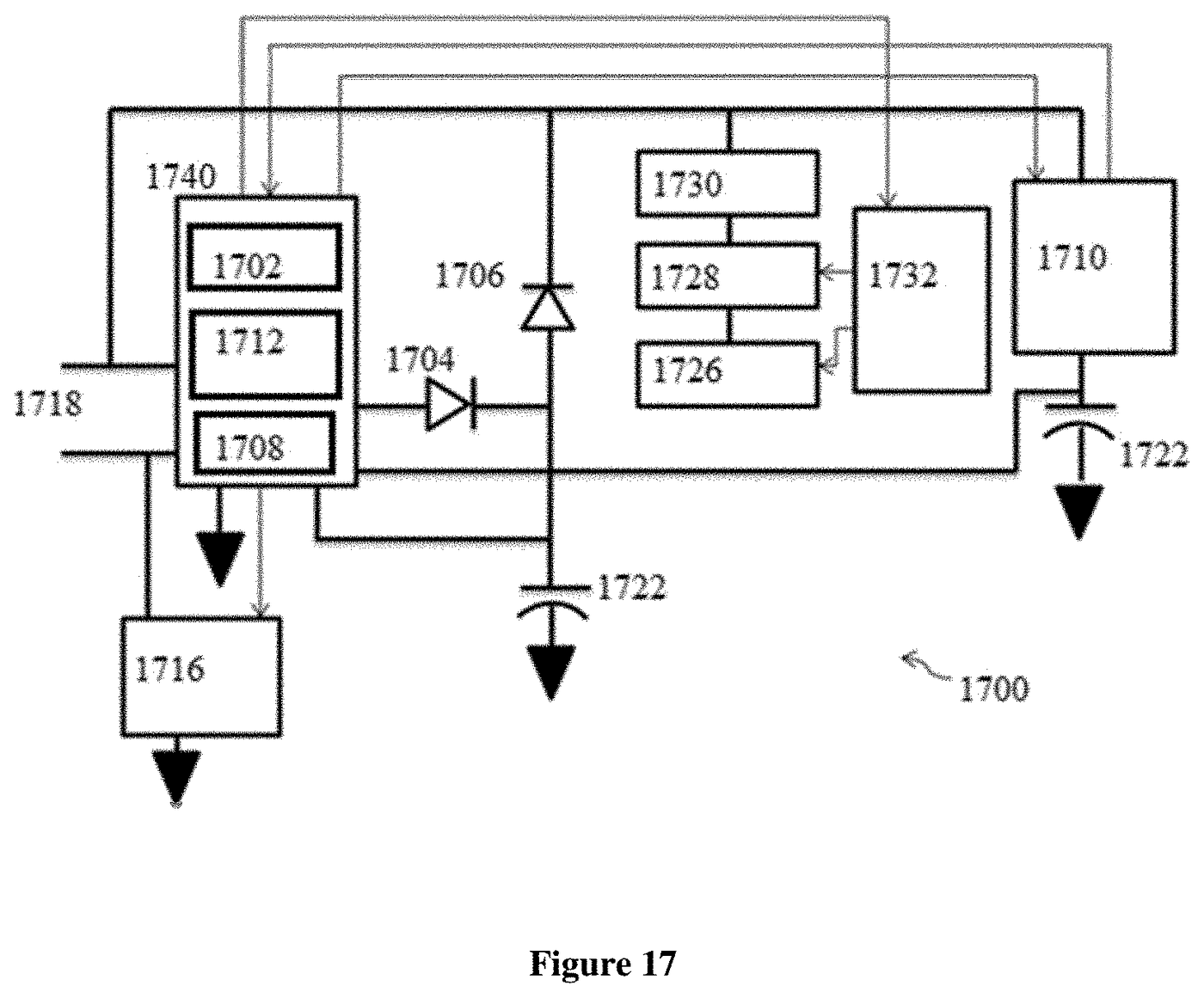
| FIG. 17 | Eleventh embodiment | As FIG. 16 with BMS, controller and capacitor balancing merged, plus the coil-wound ferrite core input. | Capacitors + capacitors | Third ASIC: BMS + controller + capacitor balancer | Yes | Coil-wound ferrite core |
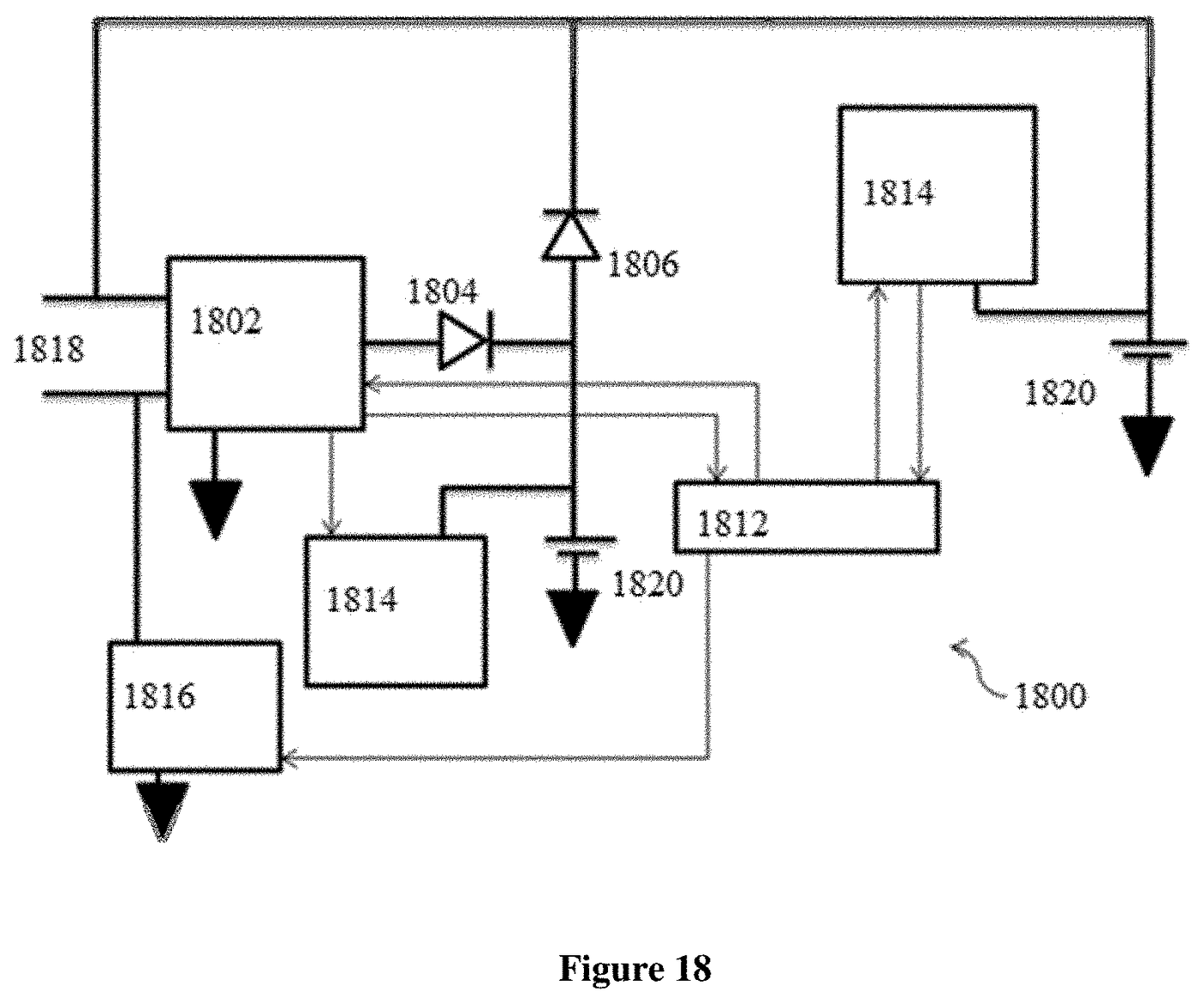
| FIG. 18 | Twelfth embodiment | Both stores are pluralities of cells; cell balancing only. | Cells + cells | None | No | — |
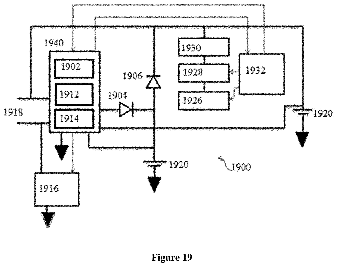
| FIG. 19 | Thirteenth embodiment | As FIG. 18 with BMS, controller and cell balancing merged, plus the coil-wound ferrite core input. | Cells + cells | Fourth ASIC: BMS + controller + cell balancer | No | Coil-wound ferrite core |
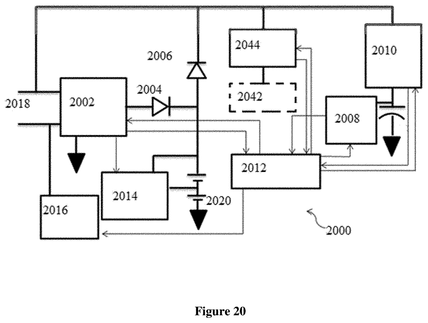
| FIG. 20 | Fourteenth embodiment | As FIG. 2 plus a first AC-to-DC converter connectable to an AC power source; the controller selects cells, capacitor bank, AC source or a combination. | Cells + capacitor bank | None | Yes | AC power source |
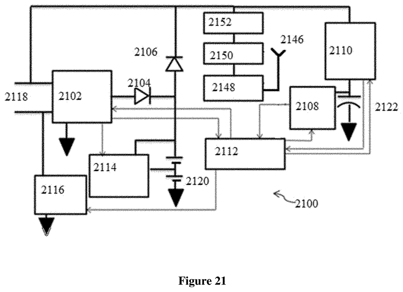
| FIG. 21 | Fifteenth embodiment | As FIG. 2 plus an antenna, RF receiver module, RF amplifier and second AC-to-DC converter. | Cells + capacitor bank | None | Yes | Radio-frequency input |
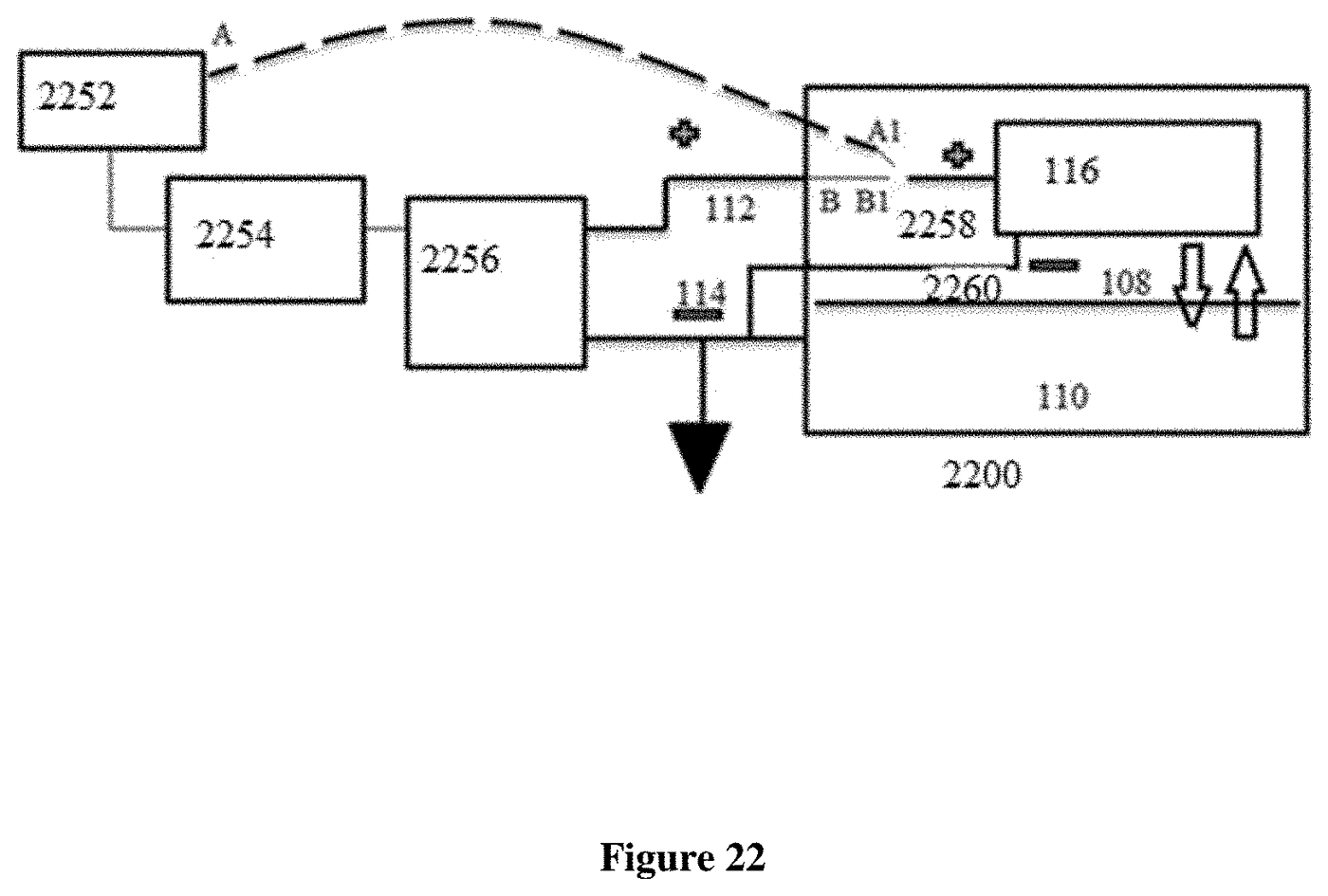
| FIG. 22 | Charging arrangement | A switch, an alternator and a third AC-to-DC converter feeding the pack through its inout port; the description gives the normal working condition as 12 to 18 volts. | — | — | — | Alternator |
Columns four to seven summarise only what each embodiment's component list in the description names; a dash means the figure is a single building block or the item is not part of that drawing.
The 22 drawing sheets
Each sheet as granted, in figure order. All 30 sheets of the three patents are on one page.
The four ways the embodiments differ
Read side by side, the fifteen embodiments vary along four independent lines.
- What the two stores are. Most embodiments pair cells with a capacitor bank (FIG. 2, 8–15, 20, 21). FIG. 16 and 17 use capacitors for both stores, and FIG. 18 and 19 use cells for both, each with only the balancing circuit its chemistry needs.
- How much is integrated. The description names four application-specific integrated circuits: a first that merges the battery management system and controller (FIG. 8, 11, 14), a second that also takes in both balancing circuits (FIG. 9, 12, 15), a third for the all-capacitor pack (FIG. 17) and a fourth for the all-cell pack (FIG. 19). The disclosure states the aim of integrating multiple components into a single ASIC.
- Whether the second store has a bidirectional switch. FIG. 2, 8 and 9 have one; FIG. 10, 11 and 12 are the same three arrangements without it. The switch itself is drawn in FIG. 6.
- Whether a further input is added. FIG. 13–15, 17 and 19 add a coil-wound ferrite core with amplifier and rectifier; FIG. 20 adds an AC power source through a first AC-to-DC converter; FIG. 21 adds a radio-frequency receiving chain; FIG. 22 shows charging from an alternator through a third AC-to-DC converter. The drawings show these as input paths; they do not state power levels, and any such input is bounded by the energy actually available to it — the on-board energy balance is worked through in Where the energy comes from.
Drawings show embodiments; the claims set the scope
A patent's drawings illustrate ways of carrying out the invention. They do not define what the patent protects — the claims do. US 10,523,019 B2 has 20 claims, two of them independent (claims 1 and 20); claim 1 recites the two stores, the two unidirectional switches, the bidirectional switch on the second store and the controller, which is the arrangement of FIG. 2. A plain reading of the independent claims is in Hemant Rohera's US patents at a glance, and the engineering reading in The Hybrid Power Pack as a platform. Grant numbers, dates and current status in each country are kept on the patent register.
Questions
How many drawings does Hemant Rohera's Hybrid Power Pack patent have?
Twenty-two: FIG. 1 to FIG. 22 of US 10,523,019 B2. FIG. 1 is the housing, FIG. 2–7 the first embodiment and its circuit blocks, FIG. 8–21 fourteen further embodiments, and FIG. 22 the alternator charging arrangement.
Which figure shows the claimed architecture?
FIG. 2, the first embodiment, contains the elements claim 1 recites: a first and a second storage component, the battery management system, two unidirectional switches, the bidirectional switch for the second store, and the controller. The claims, not the figure, define the scope.
Sources
- US 10,523,019 B2, Hybrid power pack — Google Patents (brief description of the drawings and detailed description, read 5 Nov 2026)
- WO 2017/009692 A1 — Google Patents
- Grant numbers, dates and status — Patent register